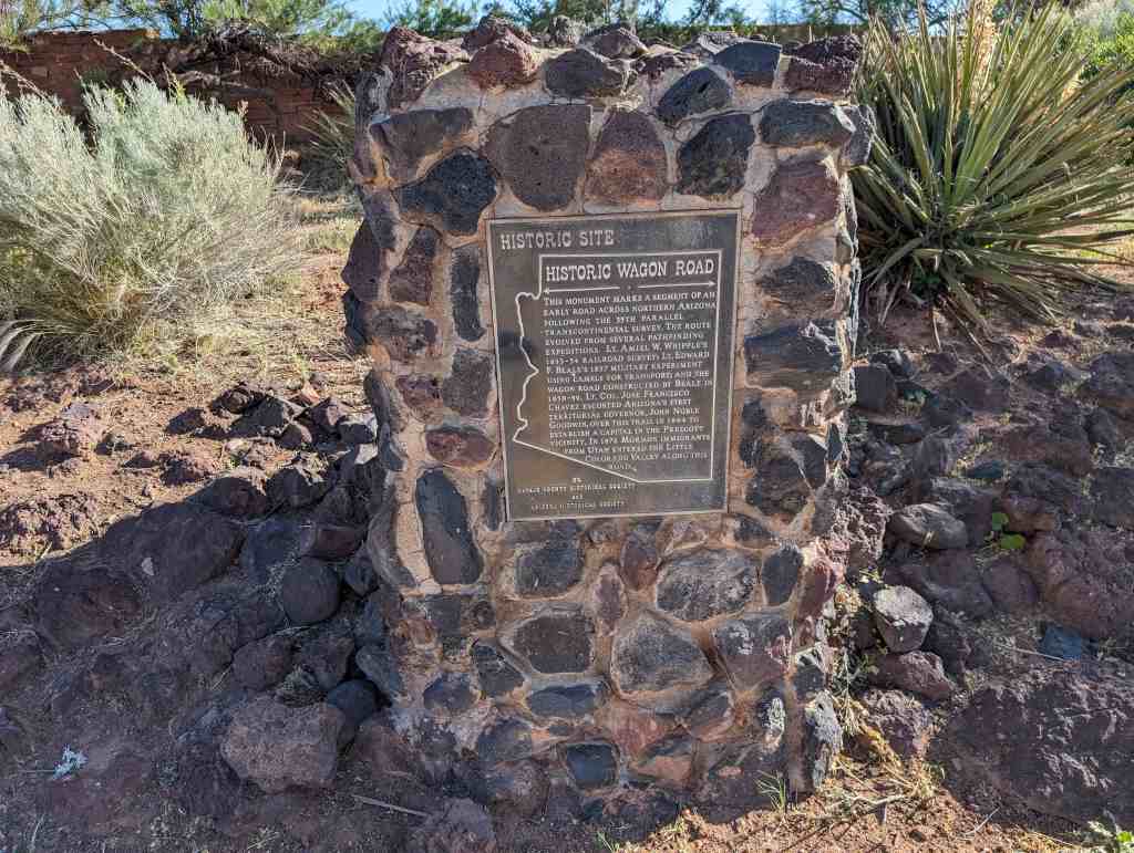
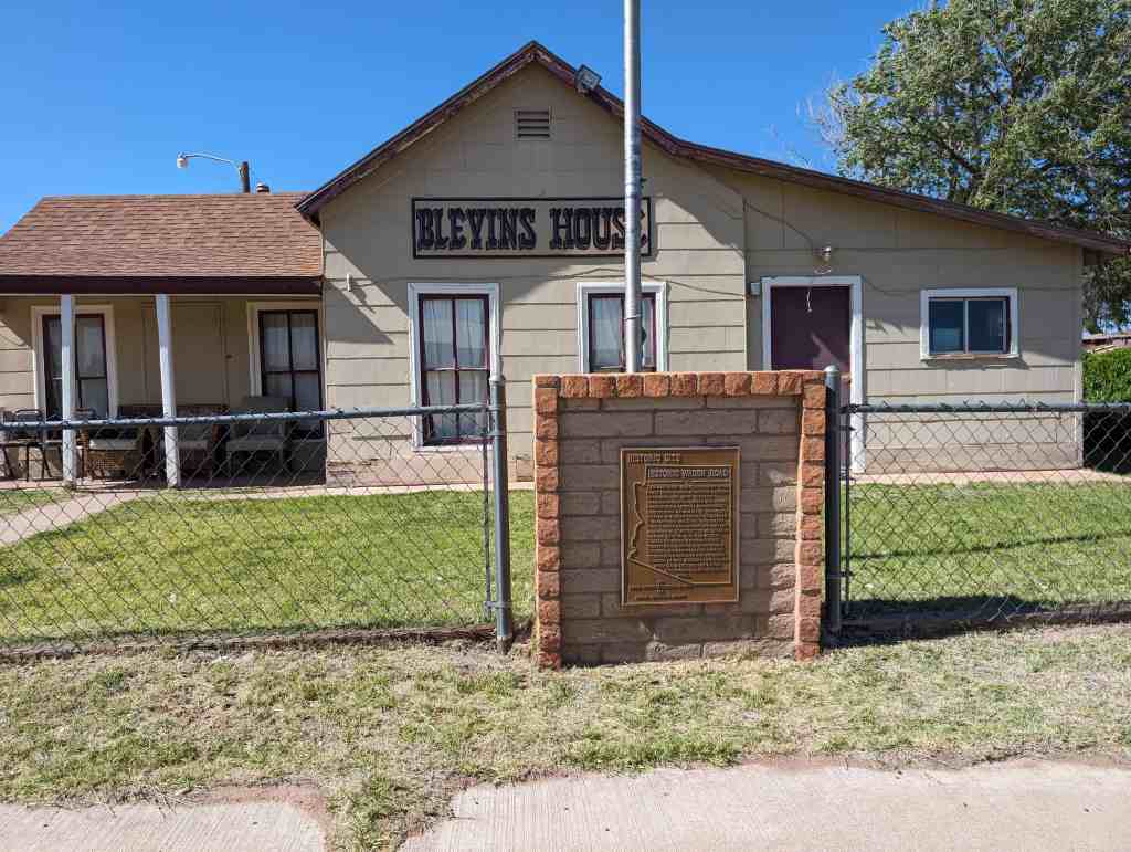
This monument marks a segment of an early road across northern Arizona following the 35th parallel-transcontinental survey. The route evolved from several pathfinding expeditions: Lt. Amiel W. Whipple’s 1853-54 railroad survey; Lt. Edward F. Beale’s 1857 military experiment using camels for transport; and the wagon road constructed by Beale in 1858-59. Lt. Col. Jose Francisco Chavez escorted Arizona’s first territorial governor, John Noble Goodwin, over this trail in 1864 to establish a capital in the Prescott vicinity. In 1876 Mormon immigrants from Utah entered the Little Colorado Valley along this road.
Located at 205 East 2nd Street in Winslow, Arizona
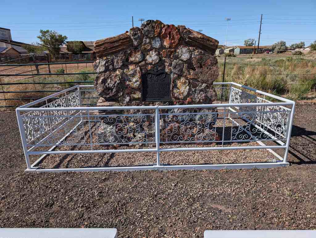
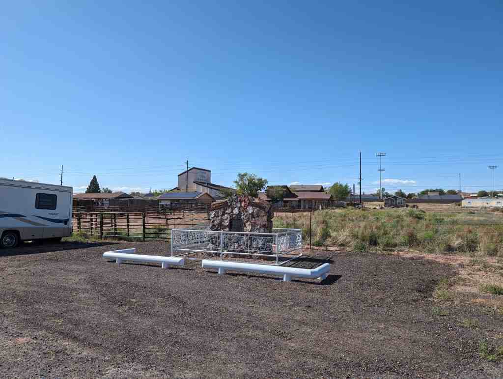
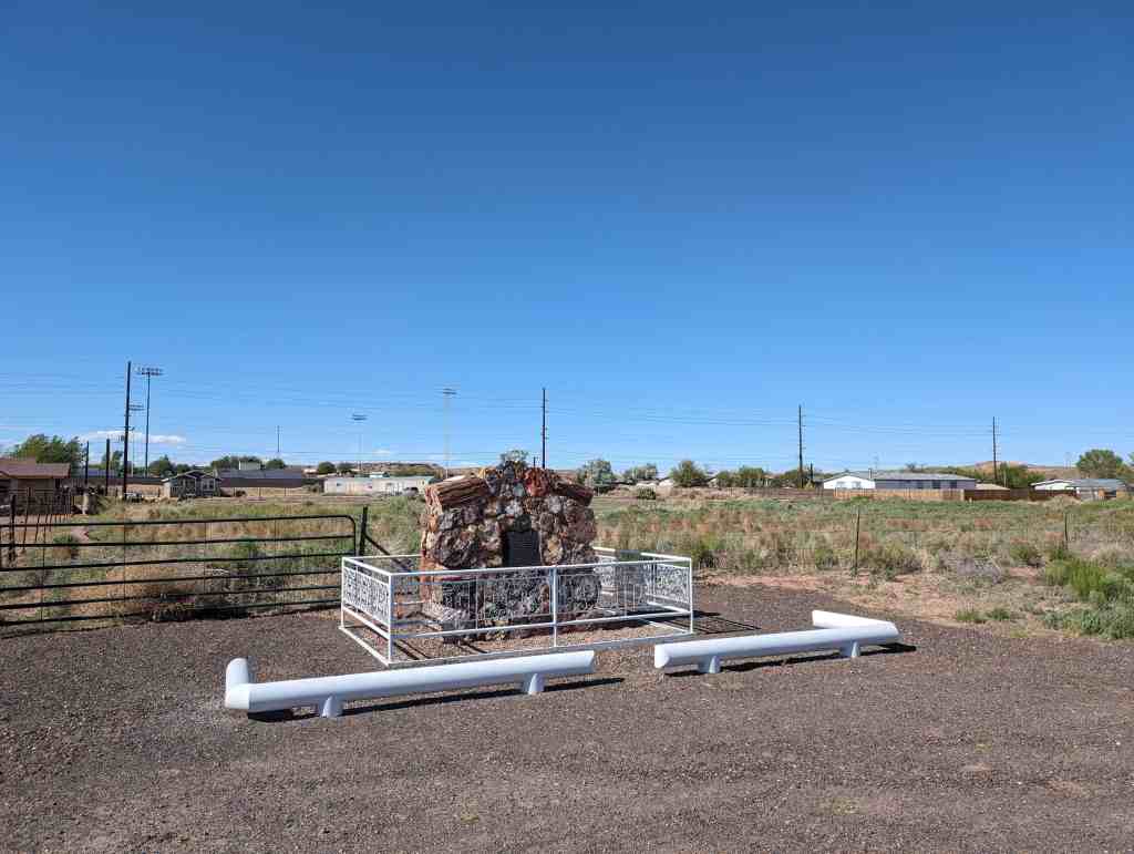
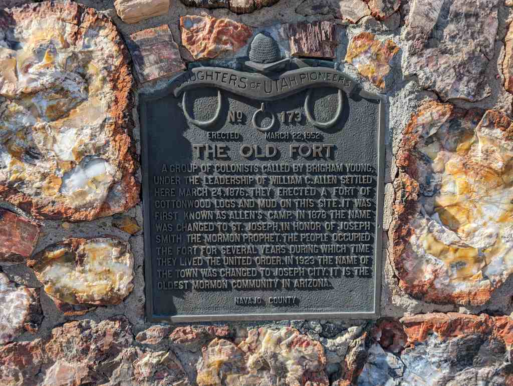
A group of colonists called by Brigham Young, under the leadership of William C. Allen settled here March 24, 1876. They erected a fort of cottonwood logs and mud on this site. It was first known as Allen’s Camp. In 1878 the name was changed to St. Joseph, in honor of Joseph Smith the Mormon Prophet. The people occupied the fort for several years during which time they lived the United Order. In 1923 the name of the town was changed to Joseph City. It is the oldest Mormon community in Arizona.
This is Daughters of Utah Pioneers historic marker #173. Erected on March 22, 1952 and located in Joseph City, Arizona.
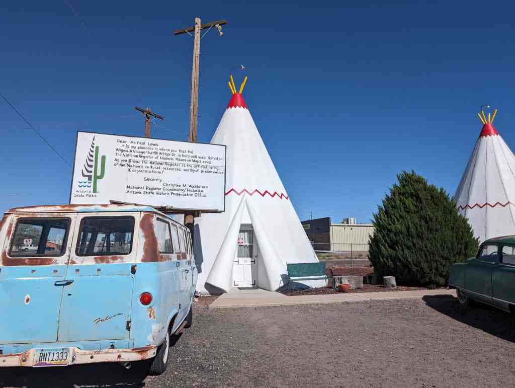
This property qualifies for listing in the National Register of Historic Places because it satisfies the registration requirements outlined in the Multiple Property Document entitled “Historic US Route 66 in Arizona (amended)” and accepted by the Keeper of the National Register on August 26,1996. The Wigwam Village #6 qualifies under the ‘Traveler Related Facilities” property type and meets the requirements of 1. Association, 2. Design, Location, and Workmanship, and 3. Feeling and Setting.
Chester E. Lewis I of Holbrook, Arizona visited a Wigwam Village in Kentucky constructed by Frank Redford. Mr. Redford had designed the architecture of his motel/café/gift shop/gas station buildings using the form and motif of Native American teepees. This use of architectural imagery by automobile service-oriented establishments along the American roadside has come to be known as place-product-packaging (Wigwam Village No. 2 National Register nomination). A detailed account of Mr. Redford’s venture can be found in Roadside America-The Automobile in Design and Culture (1990, Iowa State University Press, Jan Jennings editor, pp. 125-135). His design of wigwams or teepees was intended to be an aesthetic eye-appealing gimmick to capture the attention and patronage of the automobile masses. Mr. Redford built three villages himself and authorized the use of his blueprints for four other villages. Two of the seven were constructed along Route 66, one by Mr. Redford himself (Village #7) in San Bernardino, California, and a second by Mr. Lewis in Holbrook, Arizona. Mr. Lewis was very much impressed with Mr. Redford’s idea and success that he had observed in the 1930s, and some ten years later he visited Mr. Redford and negotiated a trade with him. For the use of his blueprints, Mr. Lewis agreed to pay Mr. Redford a royalty from his village, which was to consist of all the proceeds from the coin-operated AM radios that would be installed in the motel units at Mr. Lewis’ expense. Mr. Redford and Mr. Lewis became life-long friends.
Wigwam Village #6 was located on busy Route 66 and offered a unique place to overnight as well as to refuel the family automobile. The national prosperity and the Baby Boomers of the 1950s and 1960s often choked Route 66 with traffic during the summer vacation months including eager youngsters who cried if they didn’t get to sleep in a wigwam. Many of those youngsters, now aging, return in the 21st century to experience once again one of their childhood delights or fulfill a dream if they were denied it as a child. Only three of the seven villages still stand today, Village #2 in Cave City, Kentucky, Village #6 in Holbrook, and Village #7 in California. The Cave City Wigwam Village is listed on the National Register and the California Wigwam Village is in poor repair.
Wigwam Village #6, or the Wigwam Motel was added to the National Register of Historic Places (#02000419) on May 2, 2002 and is located at 811 W Hopi Drive in Holbrook, Arizona
The motel meets the registration requirement of the MPDF in the following ways:
1. Association. This property is related to the traveling tourist industry on Historic Route US 66. Wigwam Village #6 was designed and constructed as a motel to cater to tourists and travelers on Route 66, and it has served as such since is first opened 51 plus years ago. Chester E. Lewis I of Holbrook, Arizona constructed Wigwam Village #6 in the late 1940s on Highway US 66 in Holbrook, Arizona at 811W. Hopi Drive (Route 66). The business is currently located on Historic Route US 66 (Business 1-40) at the same address in Holbrook. Mr. Lewis opened his motel for business on June 1, 1950. Navajo County Court records in the County Clerk’s office show that Mr. Lewis, or a Lewis owned Arizona corporation or L.L.C. has paid the property taxes and owned the motel until the present day. City street plans on file at Holbrook City Hall verify that Route US 66 and Historic Route US 66 have always constituted W. Hopi Dr. in Holbrook and that it passes immediately in front of the property in question.
Originally, a set of gasoline pumps stood in front of the office. The motel was shut down from 1974 till 1988 in response to the drastically reduced flow of business through the small towns that were bypassed by the interstate highway system in the early 1970s. During this era Wigwam Village #6 did not function commercially in any other capacity except to sell gasoline until 1984. In 1988 the motel reopened and has operated as such since that time.
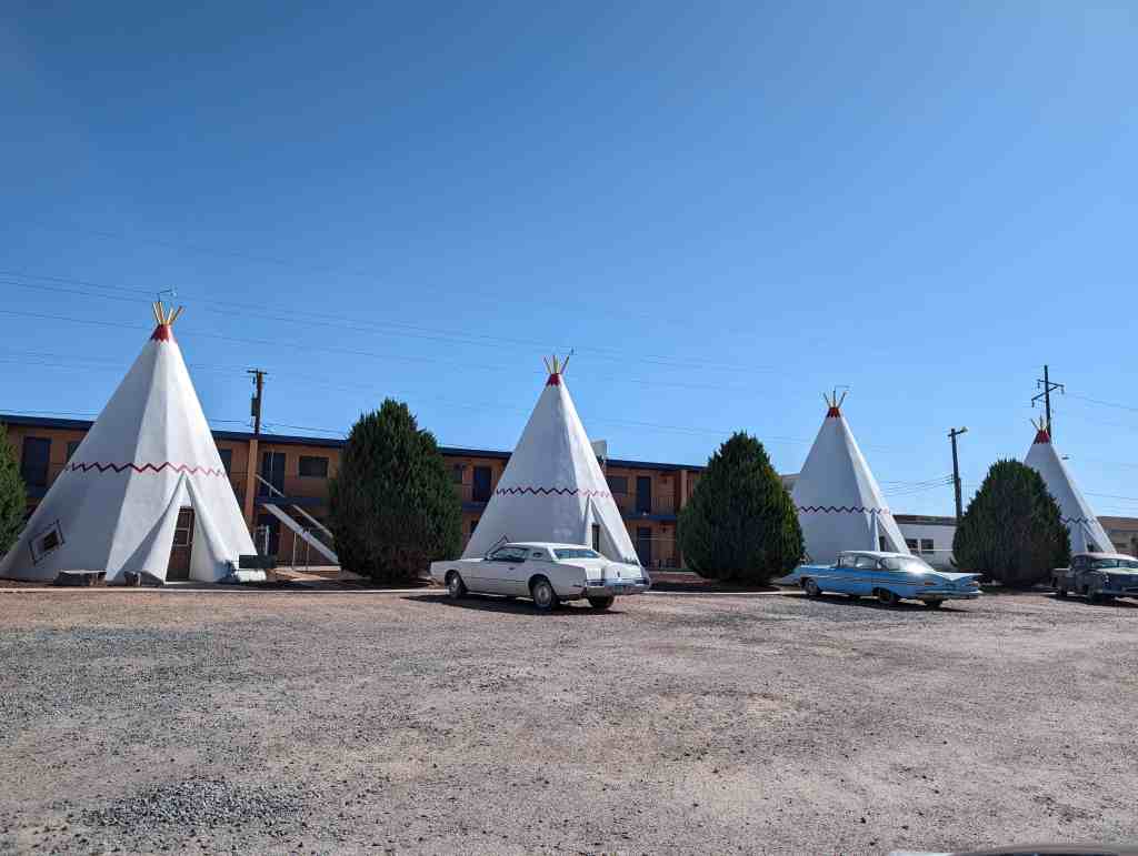
2. Design, Location, Workmanship. The design and physical layout of the 18 contributing structures of Wigwam Village #6 is identical to its original down to the colors used to paint and highlight the sleeping units, with one exception. One of the 18 structures, the 40′ X 60′ office between the two small bathroom wigwams, was originally constructed in 1955 as a large teepee that measured 30′ X 37′. The large teepee was replaced with the rectangular office building in 1956 to better serve the need of the retail gasoline sales. Although the two-story apartment building (outside the boundary of the nominated property) is readily visible behind the teepees, the building does not infringe on the original courtyard space created by the placement of the sleeping units.
The structural workmanship of the 18 contributing structures is original and that of Mr. Chester E. Lewis I. Painting and maintenance, of course, is required, and these are carried out in such a manner as to not alter the original structure. The interior design of the motel rooms has not changed although various color schemes have been used over the years, and curtains, spreads, furniture, tile, carpet, lighting fixtures, etc. have been replaced due to wear and tear. The use of Native American motifs has been maintained by using replacement items with appropriate designs. Some gas heaters have been replaced with electric ones and plumbing fixtures must be replaced from time to time, but the bathrooms still preserve the original layout of commode, sink, and shower and have the original 1950s floor tile in place. The courtyard grounds have always had a gravel cover. Playground equipment for children has been installed and removed periodically over the decades; the original 1950 courtyard did not contain any such equipment.
3. Feeling and Setting. Wigwam Village #6 retains its feeling and setting. The design of the buildings and layout has been maintained and is quite unique. As previously stated, the motel has been the subject of numerous newspaper and magazine articles over the years, with the most recent one appearing in the Arizona Republic on December 9,2001. Some tourists today make an impromptu visit to Wigwam Village #6 while some come with reservations made months in advance to enjoy the feeling and setting preserved here of the early days of the ‘Mother Road’. One tourist will visit to escape from the modernism of the day just as visitors did decades ago, another to briefly open the nostalgic capsule of his/her childhood visit when the Baby Boomers were just toddlers, another to enjoy the Indian motif of the setting, and yet another just to photograph the novelty of the village or the dumpster behind the office in which the actor Lou Diamond Phillips discards some burning papers in a scene from the movie “Dark Wind.”
As a unique example of Route 66, travel-related facilities, Wigwam Village #6 is a significant part of the history of Holbrook, Arizona, and Route 66. This family-owned business has contributed to the aura of Route 66 since 1950 and the family continues to run the motel today. Obviously unique as roadside architecture, the continued ownership by the Lewis family for over 50 years is as much a part of the story as the sign that asks “Have you slept in a wigwam lately?”
CONDITION AND INTEGRITY
The condition of Wigwam Village #6 is very good. Seventeen of the eighteen buildings are in their original state, and the quality of their condition is evidenced by the fact that the motel is open for business year round. None of the 18 buildings has undergone any major or minor structural repairs since their construction. Only the office has undergone any remodeling, as described above.
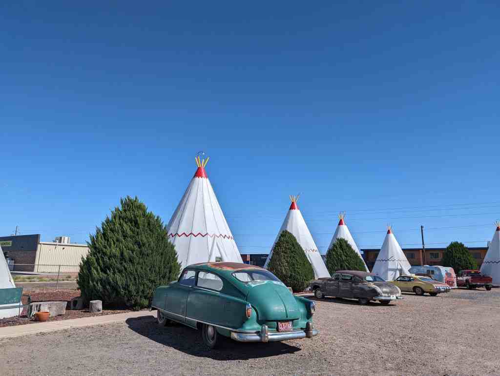
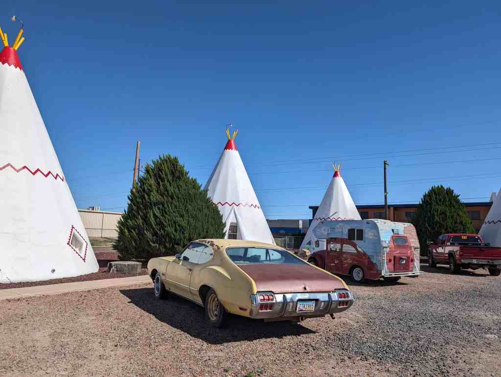
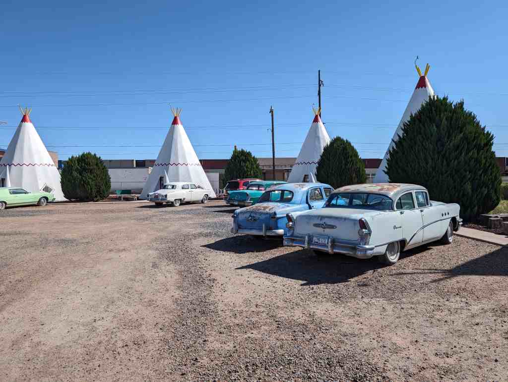
The integrity of the original motel has been maintained as there have been no significant changes to the buildings and they are in very good condition. The best evidence supporting the aesthetic integrity of the village is the feeling and association one experiences upon visiting the motel with its collection of 1950s vintage motorcars. A comparison of 1950s photographs with the village today, as well as tourists’ and residents7 testimonials, also supports the claim that the integrity of the Wigwam Village #6 is intact and well preserved, providing the same ambiance today for the traveler as in the past.
Wigwam Village #6 is nationally significant for several reasons. The Wigwam Village in Cave City, Kentucky, is the only other of these motels that yet survives intact and it is listed in the Register as nationally significant. The motel in Holbrook is related to place-product-packaging (as is the Cave City version) but moreover, it is directly related to place-product-packaging on Route 66. Acting on the idea that a unique motel would appeal to travelers on Route 66, Chester E. Lewis opened the “wigwams’7 in 1950 and this mom and pop business has been owned and operated (in some fashion) by the Lewis family ever since. Known around the world through many publications, Wigwam Village #6 is not only an icon of Holbrook and northern Arizona, but of all of Route 66, the “Mother Road.”
NARRATIVE DESCRIPTION
Wigwam Village #6 is located seven blocks west of downtown Holbrook, Arizona on Business 1-40, historic U.S. Route 66. The village is a motel consisting of individual non-connected, sleeping units built in the style of the teepees of the Plains Indians. The name, consequently, is perhaps a misnomer since ‘wigwams’ were hogan-like shelters with roofs of timbers, furs, and/or mud which did not culminate in a conical point typical of the teepees. The architect, Frank Redford, however, selected “Wigwam Village” for the title of his designed motel rather than “Teepee Village”. The former was more pleasing to him. The novel design and public display of Wigwam Village #6 has made it one of the most prominent man-made landmarks in the town of Holbrook and in all of Northern Arizona along old U.S. Route 66. Photographs in color and black & white of the Village have graced the covers of and appeared in periodicals, travel magazines, newspapers, history books, and calendars worldwide for more then a decade.
The lot has 270 feet of frontage on Business 1-40 and a depth of 230 feet. The motel itself consists of 18 contributing structures (units) arranged in a rectangle that occupies the majority of the lot. There are four units on each of the short sides of the rectangle and seven units on the back side for a total of 15 sleeping units. The remaining 3 units are concentrated in a cluster in the center on the frontage side of the lot on Bus. 1-40 and consist of the office (60′ X 40′) which is flanked by two smaller units (wigwams) that serve as bathrooms for the office. The three structures located along the back side of the lot behind the back row of the 7motel units consist of one two-story, 20-room apartment complex, a storage shed (which house spare fixtures and parts, tools, and shop space for the motel maintenance work), and a small residence. These buildings are not considered part of the nominated property.
The 15 large wigwams (units) are laid out in an open rectangle as described (see photographs) in order to resemble an Indian village. The office, with its flanking, smaller wigwams, represents the dwelling for the chief and his family. The office contains appropriate administrative facilities and a gift shop. The office also houses a museum that contains biographical data on Chester E. Lewis I, some of his collectables, a nice assortment of polished petrified wood slabs, a few 19th and 20th century firearms, and sundry items. Each of the 15 wigwams is identical in construction and measurements with an equal space between each. A 3 foot sidewalk follows the inside perimeter of the 15 wigwams passing 5 feet in front of each thus connecting all with a pathway. A short walkway connects the doorway of each unit with the sidewalk. The entire interior of the courtyard is dry landscaped with small gravel for parking and a driveway from the highway. There are 10 to 12 foot high juniper trees located between the wigwams.
Each of the 15 wigwams is a cone 21 feet wide at the base and 28 feet high to the top of the yellow 2′ pipes at the top. The base/foundation is a regular 16-sided polygon with the exception of the one side with extended tongue for the doorway exit. Each of the 16 sides form a triangle measuring 4 feet on the base and narrowing to inches at the crest where the pipes protrude from the top of the cone. All 16 triangles are anchored to the concrete foundation and to a V X 2″ iron pipe at the top. Each side or rib is numbered for architectural purposes starting with the door which is rib #1 and proceeding counterclockwise around the structure. Recessed windows are located at ribs #4 and #14. All ribs are regular equilateral triangles except #’s 1,4, & 14 where the door and windows are. These are customized, of course, to accommodate the structural penetration. The window is a diamond shape on the exterior rib. The doorway was the more difficult of the ribs to build. The edges of the doorway are sculpted with a wraparound fringe that gives the appearance of canvas or fur being turned back on itself at the opening. The exterior is a stucco finish on a wood frame furred or decked with 1″ lumber and covered with W chicken wire. Some of the Wigwam Villages in other locations were framed with angle iron that was welded together and then finished with stucco such as with Village #2, but Village #6 was all done in wood. The exterior is painted a bright white with latex paint. A border of red triangles highlights each window. Twelve feet above the base a red zigzag design circumscribes the unit. Mr. Lewis always referred to this as the “lightning of the wigwam.” The top 20″ of the cone is also highlighted in the same red color. One of the four protruding yellow pipes at the top supports a flood lamp light fixture that brings the village to life at night.
A standard 8-foot ceiling greets the visitor on the inside. This ceiling is a major support feature for the structure, and above it the remainder of the cone’s interior is hollow except for wiring, ventilation shafts, and sixteen horizontal 2″ X 4″ cross beams about 10 feet below the apex of the cone. The interior wall parallels the 68 degrees sloping wall and is utilized for wiring, plumbing, insulation, and a hot water heater. At the doorway the vertical interior wall is recessed far enough toward the center to allow the height of the wall to reach 7 feet instead of the 4 feet common to the rest of the room. This 7-foot wall is necessary to accommodate the door. Parallel to the doorway and twelve feet toward the opposite rib is an 8-foot partition that separates the bedroom from the bathroom. The commode is at one corner and the shower stall at the opposite with the sink in between mounted on the wall corresponding to rib #9. The bedroom floor is carpeted, the bathroom floors tiled, the ceiling has incandescent light fixtures. Two corner lamps are present, there are hickory chairs and a vanity, and one or two double beds occupy each room. The curtains, spreads, and comforters are of Indian design. One of the interior windows is square on the inside but the outside shape is a diamond. An air conditioning unit occupies the other window. The furniture consists of caned, handmade hickory beds, night tables, 5′ lamps, chairs, armchairs, vanity tables with stool, and hat racks all made in Indiana. A number of chairs and stools have been re-caned, and a few of the stools have been replaced, but 95% of the furniture in use today in the sleeping rooms is the very same original furniture placed in the rooms in 1950.
The two small wigwams next to the off ice/service station, which served as restrooms for the same, are designed and constructed in the very same fashion as the larger sleeping rooms. The interiors, of course, are finished differently. The small wigwams are 12′ in diameter and 17′ high. The entry door of the bathroom is 7′ X 28″. Parallel to the entrance is a partition 6′ high that divides the floor plan in half. The front half contains the lavatory mounted to the partition opposite the entrance and trash receptacles placed next to the lavatory. The rear half of the two interior halves is divided yet again in half by a 6′ partition forming two triangular ‘corners’ that occupy one-fourth of the total floor space. Each of these two corners contains a commode. The interior ceiling is a standard 8′ ceiling. The small bathroom wigwams have no side windows. The exterior is finished and painted just as the sleeping units. The interior of the two bathrooms is identical with one exception. The Ladies’ Room (Squaws) has two lavatories mounted on the wall opposite the entrance while the Men’s Room (Braves) has one lavatory and one urinal.
The office/service station was constructed in 1956 to replace the largest wigwam that originally served as office/service station. The large, office wigwam was about 30′ in diameter and 40′ high. Despite being the largest of the wigwams it was not large enough to handle the traffic of people in the office for both the motel and service station during peak business months of the year. The replacement office measures 55′ X 36′ on the front with an additional section 12′ X 36′ attached behind. This forms a rectangular building 55′ X 48′ with a 19′ X 12′ alcove at the southeast corner of the building. A garbage dumpster is located in this alcove of the building. The construction consists of a 4″ concrete slab floor with 18″ X 24″ footings, cast iron plumbing, and above ground wiring and telephone lines. All walls are 2″ X 4″ studded on 16″ centers, and the roof is a 5′ asymmetrical vaulted one with gabled sides and desert brown composition shingles. All exterior walls are finished with stucco over chicken wire on the sheathed 2″ X 4″ stud frame. The office is divided in three sections; a front 20′ section, a middle!6/ section, and the back 12′ section. The front 20′ section of the office has a 10′ X 20′ covered canopy on the east corner, open on two sides. The covered portion of the front 20′ section is the part of the office for the public business, and this part contains counters on the west side and north sides for registration and payment and a small gift shop. This front section of the office has remained the same since its construction in 1956 with the exception of minor changes in the arrangement of furniture. There are five large 5′ X 6′ pictures window along the street side of this section and one each on both sides. The interior walls are finished in varnished, tongue and groove pine paneling, the ceiling is 10′, and the floor is carpeted. Originally the floor had gray linoleum tile. Carpet was used to replace this when it wore out. The middle 16′ section of the office building houses the museum (16′ X 40′) and a manager’s office (16′ X 15′). The interior of the museum displays a medium grit plaster over chicken wire on the sheathed stud frame painted in natural white. The manager’s office has interior walls finished in pine paneling like the front, public section of the building. There is a partition between the museum and the manager’s office with a door for employees. The museum contains the memorabilia mentioned earlier. Originally this middle section was comprised of a storage area for the motel and service station and a bedroom/bathroom for workers. This was never opened to the public. In 1988 the middle section was remodeled as described, and the museum portion was opened to the public. The back 12′ section of the office building is divided in half; a washroom area on the east and a merchandise/filing storage area on the west. The back 12′ section has only an 8′ interior ceiling. This section has never been open to the public.
There is a 16′ X 16′ canopy extending street side from the very front of the office covering the driveway immediately in front of the office and the area where the island of gasoline pumps used to be. Above the canopy is an 8′ X 24′ billboard. This originally advertised the Texaco Station but was altered to advertise the motel when gasoline sales terminated. The asymmetrical, vaulted roof was added in 2000 since the flat, hot tar roof was continually leaking over the last three decades.
This monument marks a segment of an early road across northern Arizona following the 35th parallel-transcontinental survey. The route evolved from several pathfinding expeditions: Lt. Amiel W. Whipple’s 1853-54 railroad survey; Lt. Edward F. Beale’s 1857 military experiment using camels for transport; and the wagon road constructed by Beale in 1858-59. Lt. Col. Jose Francisco Chavez escorted Arizona’s first territorial governor, John Noble Goodwin, over this trail in 1864 to establish a capital in the Prescott vicinity. In 1876 Mormon immigrants from Utah entered the Little Colorado Valley along this road.
The Hoover Dam was added to the National Register of Historic Places (#81000382) on April 8, 1981. The text below is from the nomination form for the historic register.
Hoover Dam is among the largest and earliest of the Bureau of Reclamation’s massive multiple-purpose dams. By providing electric power, flood control, and irrigation waters, the dam made increased levels of population and agricultural production in large areas of the Southwest feasible, affecting not only lands near the river, but also urban centers such as Los Angeles. Hoover Dam was not the first major arch-gravity dam to be constructed. The Cheesman Dam in Denver, for example, predates it. Nor is the dam the first of the Bureau of Reclamation’s multi-purpose dams in the United States; that distinction belongs to the Theodore Roosevelt Dam, already a National Historic Landmark. Hoover Dam is, however, distinguished by its size, the size of its hydroelectric plant, and the far-reaching consequences of its construction in the agricultural, industrial, and urban development of the Southwestern United States.
In the field of hydraulic engineering, the dam is an accomplishment comparable to the Panama Canal. Hoover Dam was the highest dam in the world – 726.4 feet from bedrock to the crest – when it was constructed. Today it is still the western hemisphere’s highest concrete dam. Because of this height, it created a reservoir that could store the normal flow of the river, including all average floods, for 2 years. When filled to the maximum, it will impound more than 31 million acre-feet of water. The dam is also large enough to trap and hold the millions of tons of sediment carried by the river every year, without seriously impairing its efficiency as a reservoir or interfering with the generation of electrical power.
One of the major engineering techniques developed in was the cooling of the concrete. If the dam had been it would have taken more than a century to do so, and cracked as it cooled. Engineers solved this problem pier-like blocks and cooling the concrete by running more than 582 miles of pipe embedded in the blocks. of the chemical heat generated by the “setting up” of cooling was completed in March, 1935.
Hoover Dam’s role in the history of hydroelectric power is indicated by the fact that from 1939 until 1949, the dam’s powerplant was the largest hydroelectric powerplant in the world. It provides electrical energy for transmission to southern California, southern Nevada, and parts of Arizona, contributing to industrial and population growth in those areas. Directly or through interconnections, the Hoover powerplant has facilitated mining and minerals exploitation projects in California, Nevada, and Arizona.
Four intake towers provide for release of stored water under normal conditions and control the flow to the canyon-wall and tunnel-plug outlet works and to the power-plant turbines. Each of the intake towers is constructed on a rock bench or shelf excavated in the canyon wall and consists of an inner barrel 29 feet 8 inches in diameter surrounded by 12 radial buttresses, which accommodate the trashrack sections (gratings for retaining objects from water entering a penstock) and support the barrel. The outer diameter of each tower tapers from 82 feet at the base to 63 feet 8-7/8 inches at the top, a parapet 342 feet above the base. The towers have upper and lower gate openings, with 12 openings each. These cylinder gates, 32 feet in diameter and 11 feet high, are raised and lowered over the openings by electrically-operated stem hoists.
TUNNELS AND OUTLET WORKS
The two downstream intake towers are each connected by a header tunnel to the canyon-wall outlet works. Each of the tunnels is 41 feet in diameter and lined with 24 inches of concrete. Each is connected by four 21-foot-diameter tunnels to the powerplant turbines. Downstream from the 21-foot tunnels, the header tunnels are each connected to the canyon-wall outlet works by six 11-foot horseshoe tunnels filled with concrete.
The two upstream intake towers are connected with the inner diversion tunnels by 41-foot-diameter inclined tunnels lined with 24 inches of concrete. These inclined tunnels are each connected to the powerplant turbines by four 21-foot penstock tunnels.
The tunnels carry a system of steel plate pipes constructed by the Babcock and Wilcox Company of Barberton, Ohio. These are composed of four 30-foot-diameter headers, four branch penstocks 13 feet in diameter leading from each header to the turbines, and a 25-foot header leading beyond the penstock pipes to six smaller branch pipes connecting to the outlet valves on each side. These pipes rest on reinforced concrete piers and are anchored at both ends, at bends and manifolds, and in several intermediate areas.
The outlet works downstream from the dam regulated the reservoir and supply water for flood control and downstream use before the generator capacity was sufficient. They have a designed capacity of about 100,000 second-feet of water. At the present time the flow is 45,000 second-feet. The outlet works consist of the canyon wall outlet system and the tunnel-plug system. The canyon wall system incorporates 84-inch needle valves on each side of the canyon approximately 175 feet above the river and pointed 60° downstream. The valves are housed in reinforced concrete structures of similar design. The Arizona house is 206 feet long, 36 feet wide, and 64.5 feet in height. The Nevada house is 190 feet long, 37 feet wide, and 64.5 feet in height. The valves are protected by 96-inch Paradox emergency gates connected to the steel outlet conduits entering through the back wall of the houses.
The tunnel plug outlet works are in the inner diversion tunnels, several hundred feet from their outlet portals. They are fed by 25-foot steel outlet pipes each leading to three 13-foot branch pipes, each of which in turn leads to two 86-inch pipes which feed a total of six 72-inch needle valves protected by 86-inch emergency gates in each diversion tunnel.
POWER PLANT
The dam’s first generator began operating fully in 1936 and its last in 1961. The powerplant consists of 17 turbines with a rated capacity of 1,850,000 horsepower with an additional 7,000 horsepower provided by the two service station units. The main turbines are each equipped with a butterfly type hydraulic-rotor-operated shut-off valve at the inlet, and a 10- to 14-footdiameter turbine casing. They are of the vertical-shaft, single-runner Francis type with cast-steel spiral casings and single-piece cast-steel runners. The initial installation was composed of four 115,000-horsepower units and one 55,000-horsepower unit. These generators became operational in 1936 and 1937. The generators are of two sizes: 82,500 KV-ampere, 180 r.p.m., 60-cycle, 16,500-volt generators; 40,000 KV-ampere, 257 r.p.m., 60-cycle, 13,800-volt generators of the conventional two-guide-bearing type with thrust bearings on the top of the frame and a 50,000 KV-ampere and 90,000 KV. Inert-gas-filled outdoor-type transformers with shielded windings provide either 55,000 kilovolt-amperes at 287,500 volts or 13,333 kilovolt amperes at 138,000 volts as well as 230,000 KV and 69,000 KV. The larger transformers are water-cooled. The powerplant is immediately downstream from the dam and is a U-shaped structure 1,650 feet long, with 2 wings, each 650 feet long. The two wings are on opposite sides of the river, with offices, shops, and operating and storage rooms built across the downstream face of the dam.
CONTRACTION JOINTS AND COOLING PIPES
Radial and circumferential contraction joints divide the face of the dam into blocks ranging in size from 25 feet by 30 feet to 50 feet by 60 feet.
These extend through the slot from its upstream face to loops of 1-inch steel cooling pipes buried in the concrete of the dam at intervals of 5 feet vertically and 5 feet and 9 inches horizontally. These 1-inch pipes are arranged in coils running from the slot circumferentially to the canyon walls and returning to the slot. More than 582 miles of these cooling pipes are embedded in the concrete of the dam.
GALLERIES, VISITOR FACILITIES, AND ARCHITECTURAL ORNAMENT
The dam is pierced with galleries at 50-foot horizontal intervals from the 575-foot altitude to the 957-foot altitude, to provide for drainage and inspection. There are approximately 2 miles of galleries in the dam. Two elevator shafts drop from the dam crest to tile-lined galleries 528 feet below, which lead downstream through the dam to the central portion of the powerhouse. In addition to the elevator shaft houses at the summit of the dam, there are two similar houses containing public restrooms. All four of these structures are decorated in Art Deco style, which is also used in the parapets of the intake towers. Sculped bas-reliefs on the upstream faces of the elevator and restroom houses depict symbolic representations of power, water storage, and other themes.
A small 1,630-square-foot exhibit building was constructed in 1940 on the Nevada side of Hoover Dam. This building provided a small lobby and an 85-seat auditorium in which visitors could view a model of the Colorado River and listen to a 10-minute taped lecture. From January, 1942, to September, 1945, the exhibit building and the dam were closed to the public and were used by the U. S. Army as a military command post.
To commemorate the engineering achievement of building Hoover Dam, a memorial was placed by the dam, with its principal part on the Nevada side of the dam, close to the abutment. Rising from a black polished base is a flagstaff, 142 feet high, flanked by two winged figures that are believed to be the largest monumental bronzes ever cast in the United States, resting on a black diorite base.
In terms of acreage, agricultural use is the most significant of the kinds of development fostered by Hoover Dam. The area irrigated with water stored in or controlled by Hoover Dam is 2,279,818 acres out of a total of 16,214,239 acres supplied with water provided by the Water and Power Resources Service projects in seventeen western states. The Boulder Canyon Project, which includes Hoover Dam, represents 14 percent of those irrigated lands, yet produces 22 percent of the vegetables and 37 percent of the fruits produced on all the lands developed as a result of the Water and Power Resources Service. This production is even more significant than these average figures suggest, because it includes winter vegetables that could not be cultivated in other areas. Also, much of the finest long- staple Pima variety cotton produced in this country is grown here. The value of the crops produced in the area served by the Boulder Canyon Project was $517,127,461 in 1977-1979.
The construction of Hoover Dam also provided storage for water for the Los Angeles metropolitan area. The development of that area and of the entire coastal southern California area was accelerated by the water supply that Hoover Dam made available.
Recreational and retirement developments have grown up in the areas protected by the dam. In 1936, the impoundment behind Hoover Dam became the first National Recreation Area established by Congress. This recreation area, known as Lake Mead National Recreation Area, has been one of the most visited areas of the National Park Service for a decade or more.
Regulation of the Colorado’s waters has protected some 8,000 acres of land from annual flooding, in the low-lying valleys of Arizona and Southern California. The building of the dam has also controlled the sediment deposits carried by the river. Prior to construction of the dam, the river had an annual discharge of more than 100,000 acre-feet of silt at Yuma. The build-up of silt deposits contributed to the destructive forces of floods, such as the one in 1905. If no other dams had been built on the river, Hoover Dam would retain all of the silt released by the river into the reservoir for a period of 300 years, and for more than 100 years before its storage capacity and usefulness would be seriously impaired. As other dams were constructed on the river, they also began to catch and retain silt, thereby extending the usefulness of the dam.
Prior to the building of the dam, low-lying areas in Arizona and southern California were particularly vulnerable to the high water flows of the Colorado River. The lower Colorado, like other western desert rivers, usually has high water flows in late spring and early summer. During those seasons, floods resulting from rapidly melting snows occurred frequently and caused great damage in the lower Colorado River basin each year. The river in times of flood carried immense quantities of sediment which, deposited in irrigation canals and headworks, created serious problems of water delivery and maintenance and constituted a major irrigation problem along the lower Colorado River. Following these high-water periods, the flows often dropped to only 3,000 to 4,000 cubic feet per second. These periods of low flow, infrequently interrupted by large flash floods from such tributaries as the San Juan, Little Colorado, Bill Williams, and Gila Rivers, limited the area that could be irrigated.
Levees had to be built and continuously repaired to protect the lowlands from flooding. In 1905, the river broke through a temporary cut into the Imperial Canal, found a new course, and poured into the Salton Sink. The Salton Sea was formed as a result, and the river caused flooding in the Imperial Valley for about 16 months. Railroad tracks and highways were washed away, and agricultural lands destroyed. Damage amounted to millions of dollars. In 1909, the Colorado River again took a new course, causing Congress to authorize a milliondollar levee project. From 1906 to 1924 a total of $10 1/4 million was spent on levee work along the lower Colorado River.
Soon after the Reclamation Act became law in 1902, reclamation engineers began a series of studies of the Colorado River. A 1922 report to Congress on the condition and potential for irrigation of California’s Imperial Valley and a 1924 study both recommended construction of a dam at or near Boulder Canyon on the Colorado. In 1928, the Boulder Canyon Project Act became law, authorizing construction of a dam at Black or Boulder Canyon for purposes of flood control, improved navigation, storage and delivery of the Colorado’s waters, and electrical energy generation. The bill also authorized construction of an Ail-American Canal System connecting the Imperial and Coachella Valleys with the Colorado.
The proposed dam was of such magnitude that there was serious opposition and concern about the economic feasibility of the project and the engineering expertise needed. Some raised the possibility of the dam’s collapse. Contributing to construction problems were the remoteness of the dam site, the ruggedness of the surrounding terrain, and the extreme climatic conditions (summer temperatures of 125° in the canyon, cloudbursts, high winds, and sudden floods).
Planning for the dam went forward, however. In 1931, the labor contract for building the dam was awarded to Six Companies, Inc., of San Francisco. The crest height of the dam was reached in March, 1935, and placement of concrete was complete by May of that year.
GENERAL DESCRIPTION:
Hoover Dam is a concrete arch-gravity storage dam. The water load in this type of dam is carried both by gravity action and by horizontal action. The dam is in the Black Canyon on the Colorado River. The west wall of this canyon is in Clark County, Nevada, and the east wall is in Mohave County, Arizona. The dam is about 28 miles southeast of Las Vegas, Nevada, and approximately 7 miles east of Boulder City, Nevada.
The drainage area above Hoover Dam comprises 167,800 square miles including parts of the states of Wyoming, Utah, Colorado, Nevada, Arizona, and New Mexico. The Colorado River above Hoover Dam rises in the Rocky Mountains of Wyoming and Colorado and flows southwestward to Lake Mead for a distance of about 900 miles. Along this stretch of the river, principal tributaries are the Green, Yampa, White, Uinta, Duchesne, Price, San Rafael, Muddy, Fremont, Escalante, Gunnison, Dolores, San Juan, Little Colorado, and Virgin Rivers.
The first concrete in Hoover Dam was placed on June 6, 1933, and the last on May 29, 1935. The dam was dedicated September 30, 1935, and was completed two years ahead of schedule.
Hoover Dam is 1,244 feet long at the crest, where U. S. Highway 93 surmounts it. Its maximum height is 726.4 feet, measured from the lowest point of the foundation rock to the crest. The dam is 660 feet thick at the base and tapers to 45 feet thick at the top. 3.25 million cubic yards of concrete were used in the dam itself.
Four diversion tunnels were built on each side of the river to drain the dam site for construction. Each is a circular tunnel 50 feet in diameter and lined with three feet of concrete. The combined length of the tunnels is 15,946 feet. Since completion of the dam, these tunnels have been plugged, sealing off the upper portions while leaving the lower portions open. These serve as spillways in the case of the two outer tunnels and as penstocks in the case of the two inner tunnels. The spillways were designed to carry 400,000 second-feet of water and include a concrete-lined 600-foot inclined tunnel leading to the diversion tunnels on each side. Gravity dams of overflow profile were constructed to serve as spillway weirs; these are 85 feet high on the Arizona side and 75 feet high on the Nevada side. Piers at quarter points on the crests of these overflow sections divide them into 100-foot sections for structural steel drum gates to control spillover. The spillway channels are 125 feet wide at the weir crest and 165 feet wide at the tunnel end. They include more than 127,000 cubic yards of concrete.
For many centuries Native Americans used this trail as a trade route to traverse the high country from the Hopi Mesas to the Verde Valley. During the mid-1800s, the United States Army, commercial companies, mail routes used portions of this trail, along with early Mormons migrating from Utah and Idaho.
Note: Due to the deteriorated condition, the Forest Service removed this marker and the monument is retired.